Pages

Sunday 24 February 2013

Instruments And Materials Of Drawing

  • INTRODUCTION
Various drawing instruments are used for making all drawings. The quality of a drawing depends on the quality of drawing instruments and drawing materials used. The drawing instruments need proper care and right adjustment. An engineering student must have complete knowledge of  drawing instrument and materials. This topic mainly deals with the basic knowledge of drawing instruments and materials, along with their uses.

  • Instruments Or Drawing
The following drawing instruments are required for preparing a neat and correct drawing.
  • Basic Instruments

  1. Drawing board
  2. Drawing sheet
  3. Drawing pencil
  4. Drawing clips or pins
  5. Eraser
  6. Eraser shield
  • Instruments for Drawing Straight Lines
  1. T- square
  2. Set- squares
  • Instruments For Drawing Curved Lines    
  1. Large size compass
  2. Small bow compass 
  3. French curve
  • Instruments For Measuring Distance
  1. Large size divider
  2. Small bow divider
  3. Scales
  • Instruments For Measuring Angles      
  1. Protractors
  2. Set-squares
  • Special Tool


  1. Mini drafter

  • Drawing Board :- A drawing board with its working surface upward. The top surface of the board is perfectly smooth and level. The bottom of the drawing board. A drawing board is rectangular in shape and is made of well seasoned soft wood such as oak or pine. A straight ebony edge is fitted on the left side on the board against which the head of the T- square moves.

Drawing Board (Top)             Drawing Board (Bottom)
  • Drawing Sheet :- The drawing is frequently made in pencil on the drawing sheet. The best drawing sheet has the following qualities:
  1. Light cream buff in colour to have good appearance
  2. Fine grains to pick up the graphite and produce clean, dense black lines
  3. Strong fibers
  4. Superior erasing qualities
  5. Folding strength
  6. Toughness
  7. Smooth surface
  8. Hard surface
  • Drawing Pencil :- Neatness, quality and accuracy of the drawing greatly depends upon the type and conditions of the pencil used for drawing. Pencil leads are made of graphite with clay added in varying amounts to make 18 grades from 9H to 7B. These grades can be divided in three groups:

  1.             Hard : 9H to 4H
  2.             Medium : 3H to B (3H, 2H, H, F, HB and B)
  3.             Soft :  2B to 7B
Pencil of 9H is the hardest and that of 7B is the softest. Harder pencils have leads of small diameters and softer pencils of larger diameters to give adequate strength. The choice of grade of pencil depends upon the type of work, texture of paper, atmosphere, humidity, etc. Following pencils should be used for drawing work in class:
  1. 2H Pencil - For drawing outlines, Centre lines, Break lines, etc.
  2. H Pencil - For dimensioning, arrowheads, hatching lines, lettering, sketching, circles, arcs, etc.
  3. Micro tip pencil - 0.5 mm for drawing outlines and 0.8 mm for shading and sketching           
  • Drawing Clips Or Pins :- Drawing clips or pins are used to fix the drawing sheet on the drawing board at the required place.  Frequent use of pins cause formation of impressions of pin pricks on the board, thus spoiling the surface of the board. The present trend is to go in for steel clips, if the size of the drawing paper is the same as that of the drawing board. Clips are used at all the four corners of the drawing board to clamp the paper. Adhesive tapes are also used for fixing the drawing sheet.
  • Eraser :- Eraser is used to remove the extra lines, lines/marks drawn by mistake and to clear soiled spots on the drawing. Only pencil eraser is used.  Soft India-rubber is the most suitable kind of eraser for pencil drawings. The eraser used should be such that the surface of the drawing paper is not spoiled in anyway. It is desirable to use erasing shield to protect the near by lines from being erased. The rubber crumbs formed after erasing should be swept away with a clean duster and should never be brushed off with hands. Use of eraser should be minimized by proper planning.


  • Erasing Shield :- It is a thin metal or plastic plate cut with slots, circles and curves of different dimensions. It helps to erase unwanted pencil lines without erasing the surrounding lines. 

  • T- Square :- It is composed of a long strip called blade, which is screwed rigidly at right angle to a shorter piece called head or stock.  It is made of mahogany or pear wood, which is harder than the board wood. The head also has an ebony edge which slides against the working edge of the board. T- Square is used for making horizontal, vertical, inclined or parallel lines on the drawing sheet.

  • Set-Squares :- Set-squares are made of transparent plastic and are available in the shape of triangles, having a French curve or simply a gap cut in the body. These are used for drawing short straight lines, measuring and drawing certain angles. A good combination of set-squares is 30O x 60O set square with a long edge of 250 mm and a 45set squares with each edge of 200 mm.

  • Large Size Compass :- The compass is used for drawing circles and arcs. It consists of two legs hinged together at its upper end. A pointed needle is fitted at the lower end of one leg, while a pencil lead is inserted at the end of the other leg. The lower part of the pencil leg is detachable and it can be interchanged with a similar piece containing an inking pen. Both the legs are provided with knee joints. Circles up to about 120 mm diameter can be drawn with the legs of the compass kept straight. For drawing smaller circles, both the legs should be bent at the knee joints so that these are perpendicular to the surface of the paper.                 

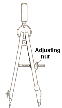
  • Small Bow Compass :- Small bow compass is conveniently used for drawing circles and arcs of small diameters. It is very handy when a number of small circles of the same diameter are to be drawn. The adjusting nut of the small compass may be on the side or at the centre. This adjusting nut is provided to make fine adjustment for accurate small circles.

  • French Curves :- French curves are used to draw irregular curved lines, which can not be drawn with a compass. A light pencil curve is first drawn free hand through the known points. Neat continuous curve is finally drawn with the longest possible curve coinciding exactly with the free hand curve. Proper care must be taken to ensure that no corners are formed anywhere on the curve. Proper use of French curves requires skill. French curves are made of transparent celluloid or plastic. These are available in various shapes. One of the french curves. 
  • Large Size Divider :- The dividers has two legs hinged at the upper end and is provided with steel pins at both the lower ends, but it does not have the knee joints.

  • The dividers are used to
  • Divide straight or curved lines into desired number of equal parts.
  • Set off distances from the scale to the drawings.
  • Transfer measurements from one part of the drawing to another.                                              

  • Small Bow Divider :- The small bow divider is adjusted by a nut and is very convenient for marking minute divisions and large number of short equal distances.
  • Scales :- Scales are made of wood, steel, celluloid or plastic. Stainless steel scales are more durable. Scale may be flat or of triangular cross- section. 15 cm long and 2 cm wide or 30 cm long or 3 cm wide flat scales are commonly used. These are usually about 1 mm thick. The longer edges of the scale are marked with inch and its sub-divisions on one side and centimeter and its sub-divisions on the other side.

  • Protractors :- Protractors or Pro-circles are used for drawing any desired angle. These are made of hard transparent plastic. The edges are either squared or beveled. Semi-circular type protractor.

  • Mini Drafter :- A T-square, protractor and set squares can be replaced by a drawing drafter. With this, lines can be drawn at any desired angle. A mini drafter is made with several links. The scale is attached at the working end of the links. The scale unit can be rotated and set at any desired angle. The clamp end is fixed to the upper or lower edge of the drawing board. There is no need to have a working edge on a drawing board when a mini drafter is used. Mini drafter saves considerable time.


  • Guidelines For Use :- The mini drafter is clamped on the board for use as follows :

  1. Set the protractor head such that zero on protractor coincides with the reference mark on index plate. Lock the head by locking knob.
  2. Insert the clamp at the left-top corner of the drawing board along horizontal or vertical edge.
  3. Align the bottom of horizontal scale along the bottom edge of the board. In this position tighten the clamp screw.
  4. Place the drawing sheet, with already drawn border lines, underneath the scales of mini drafter and align the bottom borderline of sheet with the edge of horizontal scale of mini drafter.
  5. Fix the drawing sheet in the same position by drawing clips or adhesive tape.
  6. The protractor head along with scales can be moved to any place on the drawing sheet.
  7. To draw horizontal and vertical line the reference mark should coincide with the zero on protractor head. To draw inclined line the protractor can be set to any desired angle coinciding with the reference mark on the index plate.
  8.  All the positioning is done by one hand while the other is used for drawing the lines.


  • Precautions for Neatness in Drawing Work :- Cleanliness and neatness in drawing work are very important requirements. Following precautions are required to be taken to keep a drawing neat and clean:

  1. The hands should be kept clean at all times during work.
  2. All the drawing instruments should be kept clean by wiping with a cloth/towel.
  3. Special emphasis is to be given to sliding instruments on the drawing sheet, such as T- square and set squares. These instruments must be cleaned properly every time.
  4. Pencil should always be kept sharp and used properly. It should be sharpened away from the drawing sheet and other instruments.
  5. Dirt and graphite particles from the pencil will make the drawing dirty. Hence, every care should be taken to remove them from the drawing sheet.  
  6. Direct contact of hand with the drawing sheet should be avoided.
  7. Rubbing or erasing should be done properly with soft eraser.
Problems For Practice

  1. Write the name of any 10 drawing instruments?
  2. What are the sizes of drawing boards used for sheet sizes A0, A1, A2 and A3?
  3. Draw the following angles by using T-square and Set squares :- 15⁰, 30⁰, 45⁰, 60⁰, 75⁰, 90⁰, 105⁰, 120⁰, 135⁰, 150⁰ and 165⁰?
  4. Draw the following angles with protractor :- 17⁰, 34⁰, 36⁰, 51⁰, 72⁰, 81⁰, 89⁰, 102⁰, 162⁰, and 178⁰?
  5. What are the uses of a mini-drafter. Draw the following angles with the help of a mini-drafter :- 11⁰, 22⁰, 33⁰, 44⁰, 55⁰, 66⁰, 77⁰, 88⁰, 101⁰, 114⁰, 127⁰, 141⁰, and 155⁰?
  6. Draw a name block as per ISI, for drawing sheet?
  7. Draw a layout of following drawing sheets :- A1 and A2 using reducing scale (1:5)?
  8. Draw a circle of 40 mm radius and divide it into 6 equal parts with the help of 30⁰-90⁰-60⁰ set square and T-square and mini-drafter?
  9. Write the surface area and trimmed size of drawing sheets A0, A1, A2 and A3 sizes?
  10. Draw a circle of 50 mm radius and divide into 8 equal parts by using a 45⁰-set square?
Question For Self Examination

  1. Name the different gratings of pencils?
  2. What are the uses of the following :- Drawing board, T-Square, Set Square, Protractor, Scales?
  3. What is a mini drafter and when it is used?
  4. Name a single instrument which can serve the purpose of T-Square, Set Square, Protractor and Scale?
  5. Name the instruments used to draw :- Circle, Angle, Vertical Lines, Horizontal Lines, Parallel Lines, Marking Distances?
  6. What information a title block gives?


Saturday 23 February 2013

Cams

cam is a rotating or sliding piece in a mechanical linkage used especially in transforming rotary motion into linear motion or vice-versa. It is often a part of a rotating wheel (e.g. an eccentric wheel) or shaft (e.g. a cylinder with an irregular shape) that strikes a lever at one or more points on its circular path. The cam can be a simple tooth, as is used to deliver pulses of power to a steam hammer, for example, or an eccentric disc or other shape that produces a smooth reciprocating (back and forth) motion in the follower, which is a lever making contact with the cam.
  • Overview
The cam can be seen as a device that rotates from circular to reciprocating (or sometimes oscillating) motion. A common example is the cam shaft of an automobile, which takes the rotary motion of the engine and translates it into the reciprocating motion necessary to operate the intake and exhaust valves of the cylinders.
Cams can also be viewed as information-storing and -transmitting devices. Examples are the cam-drums that direct the notes of a musical box or the movements of a screw machine's various tools and chucks. The information stored and transmitted by the cam is the answer to the question, "What actions should happen, and when?" (Even an automotive camshaft essentially answers that question, although the music box cam is a still-better example in illustrating this concept.)
  • Displacement Diagram
Certain cams can be characterized by their displacement diagrams, which reflect the changing position a roller follower (a shaft with a rotating wheel at the end) would make as the cam rotates about an axis. These diagrams relate angular position, usually in degrees, to the radial displacement experienced at that position. Displacement diagrams are traditionally presented as graphs with non-negative values. A simple displacement diagram illustrates the follower motion at a constant velocity rise followed by a similar return with a dwell in between as depicted in figure 2.[4] The rise is the motion of the follower away from the cam center, dwell is the motion where the follower is at rest, and return is the motion of the follower toward the cam center.
  • Plate Cam
The most commonly used cam is the plate cam which is cut out of a piece of flat metal or plate. Here, the follower moves in a plane perpendicular to the axis of rotation of the camshaft. Several key terms are relevant in such a construction of plate cams: base circle, prime circle (with radius equal to the sum of the follower radius and the base circle radius), pitch curve which is the radial curve traced out by applying the radial displacements away from the prime circle across all angles, and the lobe separation angle (LSA - the angle between two adjacent intake and exhaust cam lobes).
The base circle is the smallest circle that can be drawn to the cam profile.

Problems For Practice

  1. Design an edge cam to impart a rise of 35 mm at uniform velocity motion, during 180⁰ of rotation; rest during next 90⁰, and a uniform fall of 35 mm during the remaining 90⁰ of revolution. Assume base circle radius to be 35 mm and angular rotation of cam in clockwise direction?
  2. The knife edge following for a plate cam is to have the following motion, 90⁰ lift of 30 mm with simple harmonic motion then 90⁰ dwell, 180⁰ falls of 30 mm with uniform velocity. The cam is to rotate clockwise and the least cam radius is to be 50 mm. Construct the cam profile full size?
  3. A radial cam, rotating clockwise, operates an offset roller follower and gives it the following motion; 120⁰ lift of 36 mm with S.H.M. 60⁰ dwell and 180⁰ falls of 36 mm with uniform acceleration and retardation motion. Construct the cam profile, full size, if the follower center line is offset 25 mm to the cam center of rotation. The minimum radial cam thickness is to be 30 mm and the roller is 10 mm?
  4. Construct the profile of line knife edge follower for a disc cam with following motion: 180⁰ lift through 40 mm with S.H.M., 60⁰ dwell and 120⁰ fall of 40 mm with uniform acceleration and relation motion. The least radius of the cam is 20 mm and it is to rotate in an anticlockwise?
  5. Determine the profile of a cam capable of giving the roller ended follower a rise of 60 mm and a fall of 60 mm with uniform velocity motion for the one revolution of the cam. Roller diameter 25 mm, spindle diameter 50 mm, least distance from the spindle to the cam profile 20 mm. Assume the line of stroke to pass through the axis of the cam?
Question For Self Examination
  1. A cam rotating anti clock wise at uniform speed is required to give knife edge following to satisfy the following motion: - (a)    Follower to move outward through 20 mm during 120⁰ of cam rotation with acceleration & retardation motion. (b)   Follower to dwell for next 60⁰. (c)    Follower to fall the rest of the cam rotation with acceleration & retardation motion. Draw the profile or the cam displacement diagram, when the kine of the stroke of the follower passing through the center of the center of the camshaft. The minimum radius of cam = 20 cm. Use scale 1:4 or 1:5.
  2. Draw profile of  a cam  with following data :- (a)    Least radius – 30 mm. (b)   Lift of following – 30 mm.
  3. The follower is lifted with S.H.M. during 120⁰ of cam rotation, and then remains at rest for next 60⁰ and returns to the starting point during next 180⁰ of cam rotation with uniform motion. The follower is knife edged.
  4. Draw profile of cam with following data :- (a)    Least radius = 40 mm. (b)   Lift of follower = 25 mm. The follower is lifted with S.H.M. during 90⁰ of cam rotation, then remains at rest for next  90⁰ and return to the starting point during next 180⁰ of cam rotation with uniformly accelerated and retardation motion. The follower is knife edged.
  5. Design an edged cam to impart a rise of 35 mm at uniform velocity motion during 180⁰ of revolution rest during next 90⁰ and a fall of 35 mm during the remaining 90⁰ of revolution with uniform velocity motion. Assume base circle radius to be 35 mm and angular rotation of the cam in an anticlockwise direction?
  6.  Draw the profile of an edge cam to give uniform up word motion of 45 mm during the first half of the revolution and again uniform return motion through the  remaining half of the revolution. Maximum distances from cam center to the edge of the follower is 50 mm. Diameter of the shaft is 36 mm. The cam makes the wedge ended follower to reciprocate with uniform velocity motion?
  7. Draw the profile of a cam which allows the follower to oscillate with uniform angular velocity about a fixed canter. Every revolution of the cam completes one oscillation of the follower . Distance between the center of cam and roller is 35 mm. Lift = 75 mm, Lever diameter = 12 mm and length of lever = 140 mm?

Crankshaft


The crankshaft, sometimes abbreviated to crank, is the part of an engine that translates reciprocating linear piston motion into rotation. To convert the reciprocating motion into rotation, the crankshaft has "crank throws" or "crank pins", additional bearing surfaces whose axis is offset from that of the crank, to which the "big ends" of the connecting rods from each cylinder attach.
It typically connects to a flywheel to reduce the pulsation characteristic of the four-stroke cycle, and sometimes a torsional or vibrational damper at the opposite end, to reduce the torsional vibrations often caused along the length of the crankshaft by the cylinders farthest from the output end acting on the torsional elasticity of the metal.


Large engines are usually multi cylinder to reduce pulsations from individual firing strokes, with more than one piston attached to a complex crankshaft. Many small engines, such as those found in mopeds or garden machinery, are single cylinder and use only a single piston, simplifying crankshaft design. This engine can also be built with no riveted seam.
Components of a typical, four stroke cycle, DOHC piston engine. (E) exhaust cam shaft, (I) intake camshaft, (S) spark plug, (V) valves, (P) piston, (R) connecting rod, (C) crankshaft, (W) water jacket for coolant flow

  • Bearings
The crankshaft has a linear axis about which it rotates, typically with several bearing journals riding on replaceable bearings (the main bearings) held in the engine block. As the crankshaft undergoes a great deal of sideways load from each cylinder in a multicylinder engine, it must be supported by several such bearings, not just one at each end. This was a factor in the rise of V8 engines, with their shorter crankshafts, in preference to straight-8 engines. The long crankshafts of the latter suffered from an unacceptable amount of flex when engine designers began using higher compression ratios and higher rotational speeds. High performance engines often have more main bearings than their lower performance cousins for this reason.
  • Piston Stroke
The distance the axis of the crank throws from the axis of the crankshaft determines the piston stroke measurement, and thus engine displacement. A common way to increase the low-speed torque of an engine is to increase the stroke, sometimes known as "shaft-stroking." This also increases the reciprocating vibration, however, limiting the high speed capability of the engine. In compensation, it improves the low speed operation of the engine, as the longer intake stroke through smaller valve results in greater turbulence and mixing of the intake charge. Most modern high speed production engines are classified as "over square" or short-stroke, wherein the stroke is less than the diameter of the cylinder bore. As such, finding the proper balance between shaft-stroking speed and length leads to better results.
  • Engine configuration
The configuration and number of pistons in relation to each other and the crank leads to straight, V or flat engines. The same basic engine block can be used with different crankshafts, however, to alter the firing order; for instance, the 90° V6 engine configuration, in older days sometimes derived by using six cylinders of a V8 engine with what is basically a shortened version of the V8 crankshaft, produces an engine with an inherent pulsation in the power flow due to the "missing" two cylinders. The same engine, however, can be made to provide evenly spaced power pulses by using a crankshaft with an individual crank throw for each cylinder, spaced so that the pistons are actually phased 120° apart, as in the GM 3800 engine. While production V8 engines use four crank throws spaced 90° apart, high-performance V8 engines often use a "flat" crankshaft with throws spaced 180° apart. The difference can be heard as the flat-plane crankshafts result in the engine having a smoother, higher-pitched sound than cross-plane (for example, IRL Indy Car Series compared to NASCAR Sprint Cup Series, or a Ferrari 355 compared to a Chevrolet Corvette). See the main article on cross plane crankshafts.


  • Engine balance
For some engines it is necessary to provide counterweights for the reciprocating mass of each piston and connecting rod to improve engine balance. These are typically cast as part of the crankshaft but, occasionally, are bolt-on pieces. While counter weights add a considerable amount of weight to the crankshaft, it provides a smoother running engine and allows higher RPM levels to be reached.
  • Rotary Engines
Many early aircraft engines (and a few in other applications) had the crankshaft fixed to the air frame and instead the cylinders rotated, known as a rotary engine design. Rotary engines such as the Wankel engine are referred to as piston less rotary engines.
In the Wankel engine the rotors drive the eccentric shaft, which could be considered the equivalent of the crankshaft in a piston engine.

Punch Tool

punch is a hard metal rod with a shaped tip at one end and a blunt butt end at the other, which is usually struck by a hammer. Most woodworkers prefer to use a ball-peen hammer for using punches. Punches are used to drive objects, such as nails, or to form an impression of the tip on a workpiece. Decorative punches may also be used to create a pattern or even form an image.

  • Nail or pin
A nail punch also called a nail set, is used to drive the head of a nail flush with or below a surface. A pin punch is a similar tool used to drive pins for affixing a fixture to a rotating shaft. Nail and pin punches have a body by which the punch is held, with a flat ended cylindrical section whose diameter suits the object to be driven into the wood.
  • Center
A center punch is used to mark the center of a point. It is usually used to mark the center of a hole when drilling holes. A drill bit has the tendency to "wander" if it does not start in a recess. A center punch forms a large enough dimple to "guide" the tip of the drill bit. When drilling larger holes, and the web of the drill is wider than the indentation produced by a center punch, the drilling of a pilot hole is usually needed.
An automatic center punch operates without the need for a hammer.
  • Prick
A prick punch is similar to a center punch but used for marking out. It has a sharper angled tip to produce a narrower and deeper point. It is also known as a Dot punch. The mark can then be enlarged with a center punch for drilling.
  • Transfer
A transfer punch is a punch (usually in an index set) of a specific outer diameter that is non-tapered and extends the entire length of the punch (except for the tip). It is used to tightly fit the tolerances of an existing hole and, when struck, precisely transfer the center of that hole to another surface. It can be used, for example, to duplicate the hole patterns in a part, or precisely set locations for threaded holes (created by drilling and tapping) to bolt an object to a surface.
  • Doming
A doming punch is used in conjunction with a doming block to make spheres or hemispheres out of sheets of metal. The punch is generally made of tool steel, but can be made of wood. They come in a number of different sizes, the punch size determining what size the finished product will be.
  • Drift
A drift "punch" is misleadingly named; it is not used as a punch in the traditional sense of the term. A drift punch, or drift pin, or lineup punch, is used as an aid in aligning bolt or rivet holes prior to inserting a fastener. A drift punch is constructed as a tapered rod, with the hammer acting on the large end of the taper. The tapered end of a drift punch is placed into the semi-aligned bolt holes of two separate components, and then driven into the hole. As it is driven in, the taper forces the two components into alignment, allowing for easy insertion of the fastener. Unlike most punches, force is never (and should never be) applied to the tip, or end of a drift pin.
  • Roll Pin
Roll Pin Punches are used to drive roll pins. Standard Pin Punches should NEVER be used on a roll pin. Because of the hollow, thin wall construction of a roll pin, a standard pin punch will often collapse,mar or distort the end of the pin or be driven into,and jammed inside, the hollow core of the roll pin. When choosing a Roll Pin Punch, select one that is no larger than the compressed diameter of the pin. If a punch is used that is larger than the pin,the surrounding metal in which the pin is seated can be damaged.Also, a Roll Pin Punch should not be used which is smaller than the compressed diameter of the pin. If this occurs, it may be possible to drive the punch through the hollow center of the roll pin.
Roll pin punches are designed with a small projection in the center of the pin tip to support the circumference of the roll pin. The tips of Roll Pin Punches are NOT FLAT and should NEVER be used on regular solid pins. If a roll pin punch is used on a solid pin, it will mar or mark the pin.
If the end of a Roll Pin Punch is damaged or deformed, it should be discarded. It is virtually impossible to regrind the tip of the roll pin punch and properly shape the center projection. When using a Roll Pin Punch, make sure the axis of the shank of the Roll Pin Punch is in line with the axis of the roll pin. DO NOT cant the Roll Pin Punch off to one side.When you strike the Roll Pin Punch, hit it directly on the top of its head. If you strike the head of the Roll Pin Punch at an angle you may bend the shank.
  • Letter
Also known as letter stamps or number stamps. These are used to emboss the impression of a letter or number into a workpiece. They are most common in the reverse image, this allows the end result to be immediately readable, however they may be made as a positive image. This is essential in the case of die or mold making and ensures that the finished product will be readable, as a die is a negative image.

Symbols And Conventions Used In Welding Documentation

The symbols and conventions used in welding documentation are specified in national and international standards such as ISO 2553 Welded, brazed and soldered joints -- Symbolic representation on drawings and ISO 4063 Welding and allied processes -- Nomenclature of processes and reference numbers. The US standard symbols are outlined by the American National Standards Institute and the American Welding Society and are noted as "ANSI/AWS". Due in part to the growth of the oil industry, this symbol set was used during the 1990s in about 50% of the world's welding operations. An ISO committee sought to establish a global standard during this decade.
In engineering drawings, each weld is conventionally identified by an arrow which points to the joint to be welded. The arrow is annotated with letters, numbers and symbols which indicate the exact specification of the weld. In complex applications, such as those involving alloys other than mild steel, more information may be called for than can comfortably be indicated using the symbols alone. Annotations are used in these cases.
  • Component Elements

In the US, the component elements of the weld specification are:
  1. The reference line - the body of the arrow which is the baseline for the specification.
  2. The arrow tip which goes at an angle to the reference line, pointing to the joint to be welded.
  3. The tail which goes at the other end of the reference line.
  4. The basic welding symbol which goes on the reference line to indicate the shape of the weld such as a fillet or plug. The symbol is placed on the arrow side or other side of the line to indicate which side of the joint the weld goes.
  5. The dimensions and other numbers such as the length of the weld or number of spot welds go above and below the reference line.
  6. Supplementary symbols go at the junction of the reference line and the arrow tip. One such symbol is a circle to indicate an all-around weld, which goes on every side of the joint.
  7. Finish symbols go above the reference line to indicate the surface contour or finish of the weld such as flush, convex or concave.
  8. Letters indicating the welding process are placed at the tail end, such as AHW for atomic hydrogen welding. Further examples include:
  • Abbreviations For Welding Process

If a particular welding process needs to be indicated in addition to the symbols, the following abbreviations are commonly used in North America:

DesignationWelding process
CAWCarbon-arc welding
DBDip brazing
FBFurnace brazing
FWFlash welding
GMAWGas metal-arc welding
GTAWGas tungsten-arc welding
IBInduction brazing
OAWOxy-acetylene welding
OHWOxy-hydrogen welding
PGWPressure gas welding
RBResistance brazing
SAWSubmerged arc welding
TBTorch brazing
UWUpset welding

Protractor


protractor is a square, circular or semicircular tool, typically made of transparent plastic, for measuring angles. Most protractors measure angles in degrees (°). Radian-scale protractors measure angles in radians.
They are used for a variety of mechanical and engineering-related applications, but perhaps the most common use is in geometry lessons in schools.
Some protractors are simple half-discs. More advanced protractors, such as the bevel protractor, have one or two swinging arms, which can be used to help measure the angle.
  • Bevel Protractor
A bevel protractor is a graduated circular protractor with a pivoted arm; used for measuring or marking off angles. Sometimes Vernier scales are attached to give more precise readings. It has wide application in architectural and mechanical drawing, although its use is decreasing with the availability of modern drawing software or CAD.
Universal bevel protractors are also used by toolmakers; as they measure angles by mechanical contact they are classed as mechanical protractors.
The bevel protractor is used to establish and test angles to very close tolerances. It reads to 5 minutes or 1/12° and can measure any angle from 0° to 360°.
The bevel protractor consists of a beam, a graduated dial and a blade which is connected to a swivel plate (with Vernier scale) by thumb nut and clamp. When the edges of the beam and blade are parallel, a small mark on the swivel plate coincides with the zero line on the graduated dial. To measure an angle between the beam and the blade of 90° or less, the reading may be obtained direct from the graduation number on the dial indicated by the mark on the swivel plate. To measure an angle of over 90°, subtract the number of degrees as indicated on the dial from 180°, as the dial is graduated from opposite zero marks to 90° each way.
Since the spaces, both on the main scale and the Vernier scale, are numbered both to the right and to the left from zero, any angle can be measured. The readings can be taken either to the right or to the left, according to the direction in which the zero on the main scale is moved.
The above picture illustrates a variety of uses of the bevel protractor.
Reading the Vernier scale:
The bevel protractor Vernier scale may have graduations of 5′ (minutes) or 1/12°. Each space on the Vernier scale is 5′ less than two spaces on the main scale. Twenty four spaces on the Vernier scale equal in extreme length twenty three double degrees. Thus the difference between the space occupied by 2° on a main scale and the space of the Vernier scale is equal to one twenty-fourth of 2°, or 5′.
Read off directly from the main scale the number of whole degrees between 0 on this scale and the 0 of the Vernier scale. Then count, in the same direction, the number of spaces from the zero on the Vernier scale to a line that coincides with a line on the main scale; multiply this number by 5 and the product will be the number of minutes to be added to the whole number of degrees.
For example: Zero on the vernier scale has moved 28 whole degrees to the right of the 0 on the main scale and the 3rd line on the vernier scale coincides with a line upon the main scale as indicated. Multiplying 3 by 5, the product, 15, is the number of minutes to be added to the whole number of degrees, thus indicating a setting of 28 degrees and 15 minutes.


Technical Drawing Tools

Technical drawing tools are the tools used for technical drawing, including pens and rulers. Drawing tools may be used for measurement and layout of drawings, or to improve the consistency and speed of creation of standard drawing elements. Many of the tools used for manual technical drawing are obsolescent, where computer-aided drawing has become common.
  • Drawing Tools
  • Pens
Traditional and typical pens used for technical drawing are pencils and technical pens.
Pencils in use are usually mechanical pencils with a standard lead thickness. General line widths are 0.18 mm, 0.25 mm, 0.5 mm and 0.7 mm. Hardness varies usually from HB to 2H. Softer lead gives a better contrast, but harder lead gives more accurate track. Bad contrast of the lead track in general is problematic at photocopying, but new scanning copy techniques have improved the final result. Paper or plastic surfaces do require their own lead types.
"Drawing pens"
Traditional already in the 1600s used ruling pen.  
Grafos-stylus.  
A disassembled Grafos and nibs of different widths.  
Rapidograf styluses of different widths: 0.35, 0.5 and 0.7 mm.  
Rapido graph stylus parts. The head is possible to disassemble to even smaller parts  
In most cases, the final drawings are drawn with ink, on either plastic or tracing paper. The pen is generally Rapido graph-type technical pen, a marker pen that draws lines of consistent width (so-called steel marker pen). The pen has an ink container which contains a metal tube, inside which is a thin metal needle or wire, the soul. Ink is absorbed between the needle and the tube wall, preventing an excessive amount of ink from being released. The needle has a weight and by waving the pen back and forth the needle is released and the ink can run. Previously, the tank was filled from an ink bottle, newer styluses use ink cartridges.
Each line width has its own stylus. Width of the line is standardized: In Finland, the most commonly used set is 0.13 mm, 0.18 mm, 0.25 mm, 0.35 mm, 0.50 mm and 0.70 mm. There are their own style for tracing paper and plastic, because plastic requires a harder pen tip. To function well they require regular maintenance, the finest marker pens in particular
  • Drawing Board

The drawing board is an essential tool. Paper will be attached and kept straight and still, so that the drawing can be done with accuracy. Generally, different kind of assistance rulers are used in drawing. The drawing board is usually mounted to a floor pedestal in which the board turns to a different position, and also its height can be adjustable. Smaller drawing boards are produced for table-top use. In the 18th and 19th centuries, drawing paper was dampened and then its edges glued to the drawing board. After drying the paper would be flat and smooth. The completed drawing was cut free. Paper could also be secured to the drawing board with pins. More recent practice is to use self-adhesive tape to secure paper to the board. Some drawing boards are magnetized, allowing paper to be held down by long steel strips. Boards used for overlay drafting or animation may include registration pins or peg bars to ensure alignment of multiple layers of drawing media.

  • Drafting Machine

A drafting machine is a device which is mounted to the drawing board. It has rulers whose angles can be precisely adjusted with a controlling mechanism. There are two main types of apparatus: an arm-type parallelogram apparatus based on a hinged arm; and a track-type apparatus which moves on a rail mounted to the top of the drawing board. The accuracy of the arm type apparatus is better in the middle of the board, decreasing towards the edges, whereas a track machine has a constant accuracy over the whole board. The drawing head of a track-type drafting machine slides on bearings in a vertical rail, which in turn is moved along a horizontal, top-mounted rail. Both apparatus types have an adjustable drawing-head with rules attached to a protractor scale so that the angle of the rules may be adjusted.
A drafting machine allows easy drawing of parallel lines over the paper. The adjustable angle between the rulers allows the lines to be drawn in varying accurate angles. Rulers may also be used as a support for separate special rulers and letter templates. The rules are replaceable and they can be for example scale-rules.
Drawing apparatus has evolved from a drawing board mounted parallel ruler and a pantograph, which is a device used for copying objects in an adjustable ratio of sizes.

  • Rulers

Rulers used in technical drawing are usually made of polystyrene. Rulers come in two types according to the design of their edge. Straight edge can be used with lead and felt pens, whereas when technical pen is used the edge must be grooved to prevent the spread of the ink.
Architect's scale is a scaled, three-edged ruler which has six different scales marked to its sides. A typical combination for buildings details is 1:20, 1:50, 1:100, 1:25, 1:75 and 1:125. There are their own rulers for zoning work as well as for inch units. Today scale rulers are made of plastic, formerly of hardwood. A pocket-sized version is also available, with scales printed on flexible plastic stripes