INTRODUCTION
In engineering drawing, various objects have invisible or hidden interior features, which are represented by dotted lines in their projection views. But, when the features, are too many, the orthographic projections obtained get complicated and difficult to understand. In order to understand the interior view details, the object is cut an imaginary cutting plane called Sectional Plane. The part of the object between the cutting plane and the observer is assumed to be removed and view is then shown in section. The view thus obtained is called Sectional View.
Sectional View
The view obtained by cutting an object with an imaginary cutting plane is called Sectional View.
The surface produced by cutting the object by the section plane is called Section. It is indicated by thin section lines uniformly spaced, generally at an angle of 45'. As already imagined, a sectional view is a view seen when a portion of the object nearest to the observer is imagined to be removed by means of a cutting plane or planes, thus revealing the interior construction. The other views are not affected in any way always represent the entire object.
Types Of Sectional Views
The sectional views are of mainly two types. These are dependent upon the number of cutting planes cutting the object.
- Full Sectional View.
- Half Sectional View.
Full Sectional View
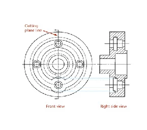
The view obtained after removing the front half portion of an object is called a Full Sectional Views or Front Sectional Views or Simply Sectional Elevation.
When the cutting plane cuts the object lengthwise, full sectional front view is obtained. It is also called longitudinal section. It may be noted that the top view or the slide remain unaffected, that means top view is drawn full not half.
The Cutting Plane
- The cutting plane is shown in a view adjacent to the sectional view.
- In the section view, the areas that would have been in actual contact with the cutting plane are show with section lining.
Lines
Behind the Cutting Plane
- The visible edges of
the object behind the cutting plane are generally shown because they are now
visible but they are not cross-hatched.
The
Cutting Plane
Placement
of Section Views
- Section views can
replace the normal top, front, side, or other standard orthographic view.
Placement
of Section Views
Labeling
Cutting Planes
- When more than one
cutting plane is used, it is especially important to label them for clarity.
Line
Precedence
- When a cutting plane
coincides with a center line, the cutting plane line takes precedence.
- When a cutting plane
line would obscure important details, just the ends of the line outside the
view and the arrows can be shown.
Rules
for Lines
- Show edges and
contours which are now visible behind the cutting plane.
- Omit hidden lines in
section views.
- A section-lined area
is always completely bounded by a visible outline.
- The section lines in
all hatched areas for that object must be parallel.
- Visible lines never
cross section lined areas.
Section
Line Mistakes
Cutting
Plane Line Style
- Cutting lines are
thick lines (0.7 mm).
- The preferred cutting
plane line style is made up of equal dashes ending in arrowheads.
Section
Line Technique
- Uniformly spaced by
an interval of about .10”
- Uniformly thin, not
varying thickness
- Do not run beyond
outer edges of the visible lines
- Usually at 45˚ angle
Section
Line Mistakes
Section
Line Technique
Section
Lining Symbols
Half
Sections
The view obtained after removing the front quarter i.e. one fourth portion of an object by means of two cutting planes at right angle to each other is called Half Sectional View or Half Sectional Elevation.
It may be observed that the plane or top view also remain unaffected i.e. full side view is drawn.


